Basic Electrical Engineering Multiple Choice Questions & Answers (MCQs),Series Circuits

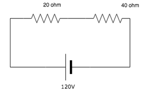
a) 1 A
b) 2 A
c) 3 A
d) 4 A
Explanation: I=V/R. Total resistance R = 20+40=60ohm. V=120V. I=120/60=2A.
2. In a series circuit, which of the parameters remain constant
across all circuit elements such as resistor, capacitor and inductor
etcetera?
a) Voltage
b) Current
c) Both voltage and current
d) Neither voltage nor current
Explanation: In a series circuit, the current across all elements remain the same and the total voltage of the circuit is the sum of the voltages across all the elements.
3. Voltage across the 60ohm resistor is______
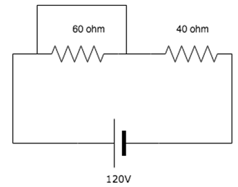
a) 72V
b) 0V
c) 48V
d) 120V
Explanation: The 60ohm resistance is shorted since current always choses the low resistance path. Voltage across short circuit is equal to zero, hence voltage across the resistor is 0.
4. Find the voltage across the 6 ohm resistor.
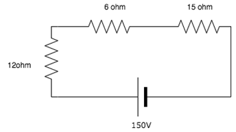
a) 150V
b) 181.6V
c) 27.27V
d) 54.48V
Explanation: Total current I=150/(6+12+15)=(150/33)V.
V across 6 ohm = 6*I = 6*(150/33)V = 27.27V.
5. If there are two bulbs connected in series and one blows out, what happens to the other bulb?
a) The other bulb continues to glow with the same brightness
b) The other bulb stops glowing
c) The other bulb glows with increased brightness
d) The other bulb also burns out
Explanation: Since the two bulbs are connected in series, if the first bulb burns out there is a break in the circuit and hence the second bulb does not glow.
6. What is the value of x if the current in the circuit is 5A?
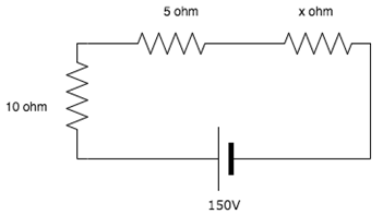
a) 15 ohm
b) 25 ohm
c) 55 ohm
d) 75 ohm
Explanation: Total voltage=sum of voltages across each resistor. =>150=10*5+5*5+5*x. Solving the equation, we get x=15 ohm.
7. A voltage across a series resistor circuit is proportional to?
a) The amount of time the circuit was on for
b) The value of the resistance itself
c) The value of the other resistances in the circuit
d) The power in the circuit
Explanation: V=IR hence the voltage across a series resistor circuit is proportional to the value of the resistance.
8. Many resistors connected in series will?
a) Divide the voltage proportionally among all the resistors
b) Divide the current proportionally
c) Increase the source voltage in proportion to the values of the resistors
d) Reduce the power to zero
Explanation: In a series circuit, the current remains the same across all resistors hence the voltage divides proportionally among all resistors.
9. What is the voltage measured across a series short?
a) Infinite
b) Zero
c) The value of the source voltage
d) Null
Explanation: A short is just a wire. The potential difference between two points of a wire is zero hence the voltage measured is equal to zero.
10. What happens to the current in the series circuit if the resistance is doubled?
a) It becomes half its original value
b) It becomes double its original value
c) It becomes zero
d) It becomes infinity
Explanation: I=V/R. If R becomes 2R then I becomes I/2 i.e. half of its original value.
This set of Basic Electrical Engineering Multiple Choice Questions & Answers (MCQs) focuses on “Power”.
1. Which of the following is not an expression power?
a) P=VI
b) P=I2R
c) P=V2/R
d) P=I/R
Explanation: Power is the product of voltage and current. Writing I in terms of V, we get P=V2/R and writing V in terms of I, we get P=I2r.
2. Which of the following statements are true?
a) Power is proportional to voltage only
b) Power is proportional to current only
c) Power is neither proportional to voltage nor to the current
d) Power is proportional to both the voltage and current
Explanation: Power is proportional to both voltage and current.
3. A 250V bulb passes a current of 0.3A. Calculate the power in the lamp.
a) 75W
b) 50W
c) 25W
d) 90W
Explanation: Here, V = 250v and I = 0.3A. P=VI. Which implies that, P=250*0.3=75W.
4. Kilowatt-hour(kWh) is a unit of?
a) Current
b) Power
c) Energy
d) Resistance
Explanation: Power is the energy per unit time. That is, P=E/t. If the unit of power in kW and the unit of time is an hour, then the unit of energy=unit of power*unit of time=kWh.
5. Calculate the power in the 20 ohm resistance.
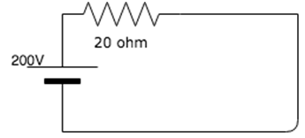
a) 2000kW
b) 2kW
c) 200kW
d) 2W
Explanation: Here V = 200v and Resistance( R) = 20ohm. P=V2/R= 2002/20=2000W=2kW.
6. A current of 5A flows in a resistor of 2 ohms. Calculate the energy dissipated in 300 seconds in the resistor.
a) 15kJ
b) 15000kJ
c) 1500J
d) 15J
Explanation: P=I2R =52*2=50W.
E= Pt=50*300=15000J=15kJ.
7. Calculate the power across each 20 ohm resistance.
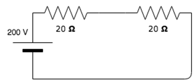
a) 1000W, 1000W
b) 500W, 500W
c) 1000kW, 1000kW
d) 500kW, 500kW
Explanation: This is a series connected circuit hence the current across each resistance is the same. To find current: I=V/R=200/20=5A.
To find power: P=I2R=52*20=500W. Since both the resistors have a resistance of 20 ohms, the power across both is the same.
8. Calculate the power across each 10 ohm resistance.
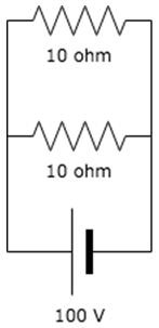
a) 1000kW, 1000kW
b) 1kW, 1kW
c) 100W, 100W
d) 100kW, 100kW
Explanation: This is parallel connected circuit, hence the voltage across each of the resistors is the same. P =(V2)/R=(1002)/10 = 1000W=1kW. Since both the resistors receive the same amount of voltage, the power in both is the same.
9. Calculate the work done in a resistor of 20 ohm carrying 5A of current in 3 hours.
a) 1.5J
b) 15J
c) 1.5kWh
d) 15kWh
Explanation: To find power: P=I2R=52*20=500W=0.5kW.
To find Work done: W=Pt=0.5*3=1.5kWh.
10. The SI unit of power is?
a) kW(kilo-watt)
b) J/s(joules per second)
c) Ws(watt-second)
d) J/h(joules per hour
Explanation: Power = energy/time
SI unit of power = SI unit of energy/SI unit of time = joule/second.
This set of Basic Electrical Engineering Multiple Choice Questions & Answers (MCQs) focuses on “Kirchhoff’s Laws and Network Solutions”.
1. Find the value of I1, I2 and I3.
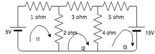
a) -0.566A, 1.29A, -1.91A
b) -1.29A, -0.566A, 1.91A
c) 1.29A, -0.566A, -1.91A
d) 1.91A, 0.566A, 1.29A
Explanation: Using the matrix method:
Matrix(3,-2,0) (I1)=(5)
(-2,9,-4) (I2)=(0)
(0,-4,9) (I3)=(-15)
Solving this matrix equation, we get I1 = 1.29A, I2 = -0.566A and I3 = -1.91A.
2. Find the value of V, if the value of I3= 0A.
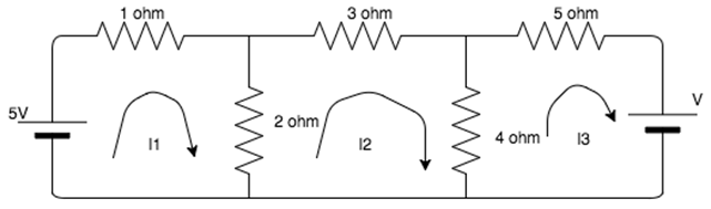
a) 1.739 V
b) 6.5 V
c) 4.5V
d)2.739V
Explanation: 5-3I1+2I2=0, 9I2-2I1=0, -4I2+V=0
On solving,V=1.739V.
3. Find the value of R if the power in the circuit is 1000W.
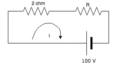
a) 10 ohm
b) 9 ohm
c) 8 ohm
d) 7 ohm
Explanation: To find the value of I:
VI=P =>100I=1000 => I=10A.
Voltage across the 2 ohm resistor = 20V.
Voltage across the R resistor = 100-20= 80V.
R=V/I => R=80/10 = 8A.
4. Find the current in the 4 ohm resistor.
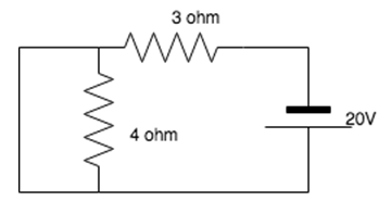
a) 5A
b) 0A
c) 2.2A
d) 20A
Explanation: The 4 ohm resistor gets shorted since current always prefers the low resistance path. All the current flows to the branch which is connected in parallel to the 4 ohm branch, hence no current flows in the 4 ohm resistance.
5. Nodal analysis is generally used to determine______
a) Voltage
b) Current
c) Resistance
d) Power
Explanation: Nodal analysis uses Kirchhoff’s Current Law to find all the node voltages. Hence it is a method used to determine the voltage.
6. Mesh analysis is generally used to determine_________
a) Voltage
b) Current
c) Resistance
d) Power
Explanation: Mesh analysis uses Kirchhoff’s Voltage Law to find all the mesh currents. Hence it is a method used to determine current.
7. What is the current in the circuit?
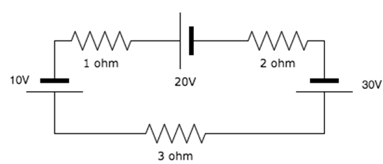
a) 0A
b) 15A
c) 5A
d) 10A
Explanation: If we move in the clockwise direction, we get the total voltage to be equal to: -10-20+30 = 0V. Since I=V/R = 0/4=0, I=0A.
8. Does the 15A source have any effect on the circuit?
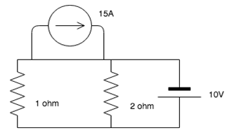
a) Yes
b) No
c) Cannot be determined
d) Yes, only when the 10V source is removed
Explanation: The 15A current source has a lower resistance path associated with it and hence it keeps moving in that particular loop. It does not leave that loop and enter the circuit, hence the circuit is not affected by it.
9. KVL is associated with____________
a) Mesh analysis
b) Nodal analysis
c) Both mesh and nodal
d) Neither mesh nor nodal
Explanation: KVL employs mesh analysis to find the different mesh currents by finding the IR products in each mesh.
10. KCL is associated with_________
a) Mesh analysis
b) Nodal analysis
c) Both mesh and nodal
d) Neither mesh nor nodal
Explanation: KCL employs nodal analysis to find the different node voltages by finding the value if a current in each branch.
This set of Basic Electrical Engineering Multiple Choice Questions & Answers (MCQs) focuses on “Norton’s Theorem”.
1. The Norton current is the_______
a) Short circuit current
b) Open circuit current
c) Open circuit and short circuit current
d) Neither open circuit nor short circuit current
Explanation: Norton current is obtained by shorting the specified terminals. So, it is the short circuit current. It is not the open circuit current because if specified terminals get open circuited then current is equal to zero.
2. Norton resistance is found by?
a) Shorting all voltage sources
b) Opening all current sources
c) Shorting all voltage sources and opening all current sources
d) Opening all voltage sources and shorting all current sources
Explanation: Ideal current sources have infinite internal resistance hence behave like an open circuit whereas ideal voltage sources have zero internal resistances hence behave as a short circuit. So, to obtain Norton resistance, all voltage sources are shorted and all current sources are opened.
3. Norton’s theorem is true for __________
a) Linear networks
b) Non-Linear networks
c) Both linear networks and nonlinear networks
d) Neither linear networks nor non-linear networks
Explanation: Norton’s theorem works for only linear circuit elements and not non-linear ones such as BJT, semiconductors etc.
4. In Norton’s theorem Isc is__________
a) Sum of two current sources
b) A single current source
c) Infinite current sources
d) 0
Explanation: Norton’s theorem states that a combination of voltage sources, current sources and resistors is equivalent to a single current source IN and a single parallel resistor RN.
5. Isc is found across the ____________ terminals of the network.
a) Input
b) Output
c) Neither input nor output
d) Either input or output
Explanation: According to Norton’s theorem, Isc is found through the output terminals of a network and not the input terminals.
6. Can we use Norton’s theorem on a circuit containing a BJT?
a) Yes
b) No
c) Depends on the BJT
d) Insufficient data provided
Explanation: We can use Norton’s theorem only for linear networks. BJT is a non-linear network hence we cannot apply Norton’s theorem for it.
7. Calculate the Norton resistance for the following circuit if 5 ohm is the load resistance.
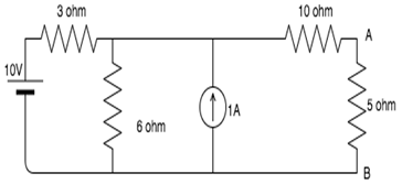
a) 10 ohm
b) 11 ohm
c) 12 ohm
d) 13 ohm
Explanation: Shorting all voltage sources and opening all current sources we have:
RN=(3||6)+10 = 12 ohm.
8. Calculate the short circuit current is the 5 ohm resistor is the load resistance.
a) 0.72A
b) 0.32A
c) 0.83A
d) 0.67A
Explanation: Since the 5 ohm is the load resistance, we short it and find the resistance through the short.
If we apply source transformation between the 6 ohm resistor and the 1A source, we get a 6V source in series with a 6 ohm resistor. Now we have two meshes. Let us consider I1 flowing in the first mesh and I2 flowing in the second mesh.
The mesh equations are:
9I1-6I2=4
-6I1+16I2=6
On solving these equations simultaneously, we get I2=0.72A, which is the short circuit current.
9. Find the current in the 5 ohm resistance using Norton’s theorem.
a) 1A
b) 1.5A
c) 0.25A
d) 0.5A
Explanation: Shorting all voltage sources and opening all current sources we have:
RN=(3||6)+10 = 12 ohm.
Since the 5 ohm is the load resistance, we short it and find the resistance through the short.
If we apply source transformation between the 6 ohm resistor and the 1A source, we get a 6V source in series with a 6 ohm resistor. Now we have two meshes. Let us consider I1 flowing in the first mesh and I2 flowing in the second mesh.
The mesh equations are:
9I1-6I2=4
-6I1+16I2=6
On solving these equations simultaneously, we get I2=0.72A, which is the short circuit current.
Connecting the current source in parallel to RN which is in turn connected in parallel to the load resistance=5ohm, we get Norton’s equivalent circuit.
Using current divider: I = 0.72*12/(12+5) = 0.5 A.
10. Which of the following is also known as the dual of Norton’s theorem?
a) Thevenin’s theorem
b) Superposition theorem
c) Maximum power transfer theorem
d) Millman’s theorem
Explanation: Thevenin’s theorem is also known as the dual of Norton’s theorem because in Norton’s theorem we find short circuit current which is the dual of open circuit voltage-what we find in Thevenin’s theorem.
This set of Basic Electrical Engineering Multiple Choice Questions & Answers (MCQs) focuses on “Capacitors”.
1. What is the relation between current and voltage in a capacitor?
a) I=1/C*integral(Vdt)
b) I=CdV/dt
c) I=1/CdV/dt
d) I=Ct
Explanation: Current=rate of change of charge
I=dQ/dt. Q=CV. C(capacitance) is constant for a given capacitor so I=CdV/dt.
2. If 2V is supplied to a 3F capacitor, calculate the charge stored in the capacitor.
a) 1.5C
b) 6C
c) 2C
d) 3C
Explanation: Q is directly proportional to V. The constant of proportionality in this case is C, that is, the capacitance. Hence Q=CV.
Q=3*2=6C.
3. Calculate the current in the capacitor having 2V supply voltage and 3F capacitance in 2seconds.
a) 2A
b) 5A
c) 6A
d) 3A
Explanation: Q is directly proportional to V. The constant of proportionality in this case is C, that is, the capacitance. Hence Q=CV.
Q=3*2=6C.
I=Q/t = 6/2 = 3A.
4. A 4microF capacitor is charged to 120V, the charge in the capacitor would be?
a) 480C
b) 480microC
c) 30C
d) 30microC
Explanation: Q is directly proportional to V. The constant of proportionality in this case is C, that is, the capacitance. Hence Q=CV.
Q=4*120=480microC.
5. For high frequencies, capacitor acts as _________
a) Open circuit
b) Short circuit
c) Amplifier
d) Rectifier
Explanation: Capacitive impedance is inversely proportional to frequency. Hence at very high frequencies, the impedance is almost equal to zero, hence it acts as a short circuit and there is no voltage across it.
6. For very low frequencies, capacitor acts as ________
a) Open circuit
b) Short circuit
c) Amplifier
d) Rectifier
Explanation: Capacitive impedance is inversely proportional to frequency. Hence at very low frequencies the impedance is almost infinity and hence acts as an open circuit and no current flows through it.
7. A capacitor consists of_________
a) Two conductors
b) Two semiconductors
c) Two dielectrics
d) Two insulators
Explanation: A capacitor consists of two conductors connected in parallel to each other so that it can store charge in between the plates.
8. Capacitor preferred when there is high frequency in the circuits is __________
a) Electrolyte capacitor
b) Mica capacitor
c) Air capacitor
d) Glass capacitor
Explanation: Mica capacitors are preferred for high frequency circuits because they have low ohmic losses and less reactance.
9. Capacitance increases with ________
a) Increase in plate area
b) Decrease in plate area
c) Increase in distance between the plates
d) Increase in density of the material
Explanation: Capacitance is directly proportional to the plate area. Hence as the plate area increases, the capacitance also increases.
10. Capacitance increases with __________
a) Increase in distance between the plates
b) Decrease in plate area
c) Decrease in distance between the plates
d) Increase in density of the material
Explanation: Capacitance is inversely proportional to the distance between the two parallel plates. Hence, as the distance between the plate decreases, the capacitance increases.
This set of Basic Electrical Engineering Multiple Choice Questions & Answers (MCQs) focuses on “Composite Dielectric Capacitor”.
1. Potential drop in a dielectric is equal to _______
a) Electric field strength*thickness
b) Electric field strength*area of a cross section
c) Electric field strength
d) Zero
Explanation: When a dielectric is introduced between the two plates of a parallel plate capacitor, the potential difference decreases by the value of the product of electric field strength*thickness which is the potential difference of the dielectric.
2. The electric field strength is 10N/C and the thickness of the
dielectric is 3m. Calculate the potential drop in the dielectric.
a) 10V
b) 20V
c) 30V
d) 40V
Explanation: The potential drop in a dielectric= electric field strength*area of cross section = 10*3 = 30V.
3. The electric fields of dielectrics having the same cross sectional
area in series are related to their relative permittivities in which
way?
a) Directly proportional
b) Inversely proportional
c) Equal
d) Not related
Explanation: Let us consider two plates having fields E1 and E2 and relative permittivities e1 and e2. Then, E1=Q/(e0*e1*A) and E2=Q/(e0*e2*A), where e0=absolute permittivity and A=area of cross section. From the given expression, we see that E1/E2=e2/e1, hence the electric field is inversely proportional to the relative permittivities.
4. What happens to the capacitance when a dielectric is introduced between its plates?
a) Increases
b) Decreases
c) Remains the same
d) Becomes zero
Explanation: The capacitance of a capacitance increases when a dielectric is introduced between its plates because the capacitance is related to the dielectric constant k by the equation:
C=k∈0A/d.
5. Calculate the relative permittivity of the second dielectric if
the relative permittivity of the first is 4. The electric field strength
of the first dielectric is 8V/m and that of the second is 2V/m.
a) 32
b) 4
c) 16
d) 8
Explanation: The relation between the two electric fields and the relative permittivities is:
E1/E1=e2/e1. Substituting the given values, we get e2=16.
6. What happens to the potential drop between the two plates of a capacitor when a dielectric is introduced between the plates?
a) Increases
b) Decreases
c) Remains the same
d) Becomes zero
Explanation: When a dielectric is introduced between the two plates of a parallel plate capacitor, the potential difference decreases because the potential difference of the dielectric is subtracted from it.
7. If the potential difference across the plates of a capacitor is
10V and a dielectric having thickness 2m is introduced between the
plates, calculate the potential difference after introducing the
dielectric. The electric field strength is 2V/m.
a) 4V
b) 6V
c) 8V
d) 10V
Explanation: When a dielectric is introduced between the plates of a capacitor, its potential difference decreases.
New potential difference= potential difference without dielectric-potential difference of dielectric = 10-2*2 = 6V.
8. Calculate the capacitance if the dielectric constant=4, area of cross section= 10m2 and the distance of separation between the plates is 5m.
a) 7.08*10-11F
b) 7.08*1011F
c) 7.08*10-12F
d) 7.08*10-10F
Explanation: The expression to find capacitance when a dielectric is introduced between the plates is:
C=ke0A/d. Substituting the given values in the equation, we get C = 7.08*10-11F.
9. A dielectric is basically a ________
a) Capacitor
b) Conductor
c) Insulator
d) Semiconductor
Explanation: A dielectric is basically an insulator because it has all the properties of an insulator.
10. What happens to the potential difference between the plates of a
capacitor as the thickness of the dielectric slab increases?
a) Increases
b) Decreases
c) Remains the same
d) Becomes zero
Explanation: When a dielectric is introduced between the plates of a capacitor, its potential difference decreases.
New potential difference= potential difference without dielectric-potential difference of dielectric. Hence as the thickness of the dielectric slab increases, a larger value is subtracted from the original potential difference.
This set of Basic Electrical Engineering Multiple Choice Questions & Answers (MCQs) focuses on “Magnetic Field”.
1. What is the magnetic field outside a solenoid?
a) Infinity
b) Half the value of the field inside
c) Double the value of the field inside
d) Zero
Explanation: There are no magnetic lines of force outside a solenoid, hence the magnetic field outside a solenoid is zero.
2. Which, among the following qualities, is not affected by the magnetic field?
a) Moving charge
b) Change in magnetic flux
c) Current flowing in a conductor
d) Stationary charge
Explanation: A stationary charge is not affected by a magnetic field because stationary charges do not have any velocity. Magnetic field cannot occur in a particle having zero velocity.
3. When a charged particle moves at right angles to the magnetic field, the variable quantity is?
a) Momentum
b) Speed
c) Energy
d) Moment of inertia
Explanation: When a charged particle moves perpendicular to the field, its speed remains the same whereas its velocity keeps on changing. Momentum is the product of the mass of the particle and the velocity if the particle, hence since velocity varies, momentum also varies.
4. If the flow of electric current is parallel to the magnetic field, the force will be ______
a) Zero
b) Infinity
c) Maximum
d) Half the original value
Explanation: Force is a cross product. A cross product involves the sine of the angle between them. If two quantities are parallel to each other, the angle between them is zero. Sin(0) is zero, hence force is zero.
5. The ratio of magnetic force to electric force on a charged particle getting undeflected in a field is?
a) 1
b) 0
c) 2
d) 4
Explanation: When a charged particle is undeflected in a field, the magnitude of the magnetic force and electric force acting on the particle is the same, hence the ratio is 1.
6. What is the strength of magnetic field known as ________
a) Flux
b) Density
c) Magnetic strength
d) Magnetic flux density
Explanation: Strength of magnetic field is also known as magnetic flux density. It is the amount of magnetic field lines crossing unit area.
7. Weakest force in nature is?
a) Electric force
b) Gravitational force
c) Weak force
d) Magnetic force
Explanation: Gravitational force is the weakest force in nature as it does not bind anything strongly with its help.
8. How can a magnetic field be produced?
a) Using a permanent magnet
b) Electric current
c) Using a temporary magnet
d) Using a permanent magnet or electric current
Explanation: An electric current as well as the permanent magnet produces a magnetic field whereas a temporary magnet fails to do so.
9. Can we see magnetic flux lines?
a) Yes
b) No
c) Depends on the strength of the field
d) Only when the field strength is very large
Explanation: No, we cannot see magnetic flux lines as the “lines of magnetic flux” is purely an imaginary concept to understand the magnetic field clearly.
10. Magnetic Field lines move from _______
a) North to south
b) South to north
c) West to east
d) East to west
Explanation: Magnetic field lines originate at the north pole and terminate at the south pole of the magnet.
This set of Basic Electrical Engineering Multiple Choice Questions & Answers (MCQs) focuses on “Force on a Current Carrying Conductor”.
1. What is the expression for force in a current carrying conductor?
a) F=K/r2
b) F=Kq/r2
c) F=Kq1q2/r2
d) F=Kq1q2/r
Explanation: The force in a current carrying conductor is directly proportional to the product of the two charges and inversely proportional to the square of the distance between them. Hence F=Kq1q2/r2, where K is the constant of proportionality.
2. Force in a conductor is__________ to the product of the charges.
a) Directly proportional
b) Inversely proportional
c) Not related
d) Cannot be determined
Explanation: The force in a current carrying conductor is directly proportional to the product of the two charges and inversely proportional to the square of the distance between them.
3. Force in a conductor is __________ to the square of the distance between the charges.
a) Directly proportional
b) Inversely proportional
c) Not related
d) Cannot be determined
Explanation: The force in a current carrying conductor is directly proportional to the product of the two charges and inversely proportional to the square of the distance between them.
4. Calculate the force between two charges having magnitude 3nC and 2nC separated by a distance of 2micro m.
a) 13.5N
b) 13.5kN
c) 1.35N
d) 1.35kN
Explanation: From the expression:
F=Kq1q2/r2, the value of K being 9*109, we get F=13.5kN.
5. If the flow of electric current is parallel to the magnetic field, the force will be?
a) Zero
b) Infinity
c) Maximum
d) Half the original value
Explanation: Force is a cross product. A cross product involves the sine of the angle between them. If two quantities are parallel to each other, the angle between them is zero. Sin(0) is zero, hence force is zero.
6. The ratio of magnetic force to electric force on a charged particle getting undeflected in a field is ______
a) 1
b) 0
c) 2
d) 4
Explanation: When a charged particle is undeflected in a field, the magnitude of the magnetic force and electric force acting on the particle is the same, hence the ratio is 1.
7. Weakest force in nature is __________
a) Electric force
b) Gravitational force
c) Weak force
d) Magnetic force
Explanation: Gravitational force is the weakest force in nature as it does not bind anything strongly with its help.
8. The relation between the direction of force and the direction of magnetic field is __________
a) Same direction
b) Opposite direction
c) Perpendicular
d) Unrelated
Explanation: When a conductor carries a certain value of current, the force developed in the conductor, the current in the conductor and the magnetic field in the conductor are mutually perpendicular to each other.
9. The relation between the direction of current and the direction of the force is ________
a) Same direction
b) Opposite direction
c) Perpendicular
d) Unrelated
Explanation: When a conductor carries a certain value of current, the force developed in the conductor, the current in the conductor and the magnetic field in the conductor are mutually perpendicular to each other.
This set of Basic Electrical Engineering Multiple Choice Questions & Answers (MCQs) focuses on “Magnetomotive Force and Magnetic Field Strength”.
1. What is a permeable substance?
a) Any good conductor
b) Any bad conductor
c) Any strong magnet
d) Any substance through which the magnetic lines of force can pass easily
Explanation: A permeable substance is one through which the magnetic lines of force can pass easily.
2. Materials having good retentivity are?
a) Strong magnets
b) Weak magnets
c) Temporary magnets
d) Permanent magnets
Explanation: Materials with good retentivity are permanent magnets because they can retain magnetism even when no external magnetic field present.
3. Magnetic field exists along which of the following?
a) Moving charges
b) Stationary charges
c) Copper
d) Iron
Explanation: Moving charges have a magnetic field associated with them because they have magnetic flux lines associated with it.
4. Magnetomotive force is equal to__________________
a) current * number of turns
b) current / number of turns
c) current / number of turns per unit length
d) current * number of turns per unit length
Explanation: MMF is ability to produce flux and is equal to product of current flowing and number of turns.
5. Unit of MMF is ______________
a) A/m
b) A-m
c) A
d) unitless
Explanation: MMF is equal to the product of current flowing and number of turns.
unit of Magnetomotive force = unit of current = A or ampere.
6. When a bar magnet is broken into two pieces, which of the following are true?
a) The magnet loses its magnetism
b) The magnet has only north pole left
c) The magnet has only south pole left
d) The magnet turns into two new bar magnets
Explanation: When a bar magnet is broken into two pieces, it forms two different bar magnets. This happens because the broken pieces of the magnet form a separate north and south pole for itself as monopoles do not exist.
7. When an electric current flows into the page, what is the direction of the magnetic field?
a) Clockwise
b) Anti-clockwise
c) Cannot be determined
d) Parallel to the current
Explanation: When the current flows into the page, the magnetic field is clockwise because of the right hand thumb rule, we orient our thumb into the page and our fingers curl in the clockwise direction.
8. When an electric current flows out of the page, what is the direction of the magnetic field?
a) Clockwise
b) Anti-clockwise
c) Cannot be determined
d) Parallel to the current
Explanation: When the current flows out of the page, the magnetic field is anti-clockwise because of the right hand thumb rule, we orient our thumb out of the page and our fingers curl in the anti-clockwise direction.
9. The relation between the direction of current and the direction of magnetic field is?
a) Same direction
b) Opposite direction
c) Perpendicular
d) Unrelated
Explanation: When a conductor carries a certain value of current, the force developed in the conductor, the current in the conductor and the magnetic field in the conductor are mutually perpendicular to each other.
This set of Basic Electrical Engineering Multiple Choice Questions & Answers (MCQs) focuses on “Reluctance”.
1. Reciprocal of reluctance is __________
a) Permeance
b) Susceptibility
c) Resistance
d) Conductance
Explanation: The reciprocal of reactance is permeance. It is the ability of a material to allow the passage of magnetic lines of flux.
2. Reluctance is ________________ to the length of the material.
a) Directly proportional
b) Inversely proportional
c) Not related
d) Reluctance is ________________ to the length of the material.
Explanation: The formula for reluctance is:
S = l/µ0 µr*A.
From the formula, we can see that reluctance is directly proportional to the length of the material.
3. Reluctance is ________________ to the area of cross section the material.
a) Directly proportional
b) Inversely proportional
c) Not related
d) Equal
Explanation: The formula for reluctance is:
S = l/(µ0 µr*A).
From the formula, we can see that reluctance is inversely proportional to the area of cross section of the material.
4. When the length of the material increases, what happens to reluctance?
a) Increases
b) Decreases
c) Remains the same
d) Becomes zero
Explanation: Reluctance is directly proportional to the length of the material hence as length increases, reluctance also increases.
5. When the area of cross section of the material increases, what happens to reluctance?
a) Increases
b) Decreases
c) Remains the same
d) Becomes zero
Explanation: Reluctance is inversely proportional to the area of cross section of the material hence as area increases, reluctance decreases.
6. Unit of reluctance is?
a) AWb
b) A2/Wb
c) Wb/A
d) A/Wb
Explanation: Reluctance is magnetomotive force per unit flux,
So unit of reluctance = unit of MMF / unit of magnetic flux = A/Wb.
7. The electrical equivalent of reluctance is?
a) Resistance
b) Inductance
c) Capacitance
d) Conductance
Explanation: Resistance is the opposition to the flow of charge, similarly reluctance is the opposition to the flow of magnetic flux.
8. As the magnetic field strength increases, reluctance?
a) Increases
b) Decreases
c) Remains the same
d) Becomes zero
Explanation: Reluctance is directly proportional to the strength of the magnetic field, hence as the strength of magnetic field increases, the reluctance increases.
9. As the magnetic flux density increases, the reluctance _____________
a) Increases
b) Decreases
c) Remains the same
d) Becomes zero
Explanation: Reluctance is inversely proportional to the magnetic flux density, hence as magnetic flux density increases, reluctance decreases.
10. Calculate the reluctance when the magnetomotive force is 10A turns and the flux is 5Wb.
a) 0.5A/Wb
b) 5A/Wb
c) 10A/Wb
d) 2A/Wb
Explanation: We know that:
F=ϕ*S
Substituting the given values from the question:
S=2A/Wb.
This set of Basic Electrical Engineering Multiple Choice Questions & Answers (MCQs) focuses on “Inductive and Non-Inductive Circuits”.
1. In case of Inductive circuit, Frequency is ______________ to the inductance.
a) Directly proportional
b) Inversely proportional
c) Unrelated
d) Much greater than
Explanation: The formula for frequency in an inductive circuit is:
XL=2*π*f*L.
Therefore: f is inversely proportional to L.
2. In case of Inductive circuit, Frequency is ______________ to the current.
a) Directly proportional
b) Inversely proportional
c) Unrelated
d) Much greater than
Explanation: The formula for frequency in an inductive circuit is:
XL=2*π*f*L => i=V/(2*π*f*L)
Therefore: f is inversely proportional to i.
3. In an inductive circuit, when the XL value increases, the circuit power factor?
a) Increases
b) Decreases
c) Remains the same
d) Becomes zero
Explanation: tan ϕ = XL/R and Power factor=cos ϕ
As XL increases, tan ϕ increases, ϕ increases, cos ϕ decreases and hence power factor decreases.
4. If the current and voltage are 90 degrees out of phase, the power factor will be?
a) 0
b) Infinity
c) 1
d) Insufficient information provided
Explanation: The power factor is the cosine of the angle between the voltage and the current. If the angle between the voltage and the current is 90, then cos90=0. Hence, the power factor is zero.
5. In a pure inductive circuit, the power factor is __________
a) Maximum
b) Minimum
c) 0
d) Infinity
Explanation: In a pure inductive circuit, the current is lagging by 90 degrees from the voltage. The power factor is the cosine of the angle between the voltage and the current. If the angle between the voltage and current is 90, then cos90=0. Hence, the power factor is zero.
6. If the power factor is 1/10 and the value of impedance is 20 ohm, calculate the resistance in the circuit.
a) 1 ohm
b) 2 ohm
c) 3 ohm
d) 4 ohm
Explanation: We know that:
cos(ϕ)=R/Z
R=Z cos(ϕ) = 20/10 = 2 ohm.
7. If the resistance in a circuit is 2 ohm and the impedance is 20 ohm, calculate the power factor.
a) 1/10
b) 1/20
c) 1/30
d) 1/40
Explanation: We know that:
cos(ϕ)=R/Z = 2/20 = 1/10 ohm.
8. If tan ϕ = 10 and the resistance is 2 ohm, calculate the inductive reactance.
a) 10 ohm
b) 20 ohm
c) 30 ohm
d) 40 ohm
Explanation: We know that:
tan(ϕ)=XL/R
From the given question, we find that the inductive reactance is 20 ohm.
9. What is the unit for inductive reactance?
a) Henry
b) Ohm
c) Farad
d) Volts
Explanation: Inductive reactance is nothing but the impedance. Impedance is the AC equivalent of resistance, hence the unit for inductive reactance is ohm.
10. An induced emf is said to be ________
a) Inductive
b) Capacitive
c) Resistive
d) Cannot be determined
Explanation: Any circuit in which a change of current is accompanied by a change of flux, and therefore by an induced emf, is said to be inductive.
This set of Basic Electrical Engineering Multiple Choice Questions & Answers (MCQs) focuses on “Transients in LR Networks”.
1. An RL network is one which consists of ____________
a) Resistor and capacitor in parallel
b) Resistor and capacitor in series
c) Resistor and inductor in parallel
d) Resistor and inductor in series
Explanation: An R-L network is a network which consists of a resistor which is connected in series to an inductor.
2. If the switch is opened at t=0, what is the current in the circuit?
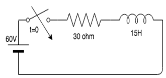
a) 0A
b) 1A
c) 2A
d) 3A
Explanation: Initially when switch was closed,current in the inductor was 60/30=2A.
Current in inductor doesn’t change suddenly so when switch is opened, current in inductor remains same i.e. 2A.
3. In an RL series circuit, when the switch is closed and the circuit is complete, what is the response?
a) Response does not vary with time
b) Decays with time
c) Increases with time
d) First increases, then decrease
Explanation: In an RL series circuit, the response decays with time because according to the equation, there is an exponential decrease in the response.
4. If the switch is closed at t=0, what is the current in the circuit?
a) 0A
b) 10A
c) 20A
d) 30A
Explanation: Initially, when the switch is open, the current in the circuit is 0. As soon as the switch is closed at t=0+, the inductor acts as an open circuit, hence the current in the circuit is zero. Since the current in the circuit is zero, there is no voltage drop across the resistor and hence voltage across the inductor is equal to the supply voltage, i.e. 60V.
5. What is the voltage across the inductor at t=0?
a) 0V
b) 20V
c) 60V
d) 58V
Explanation: Initially, when the switch is open, the current in the circuit is 0. As soon as the switch is closes at t=0+, the inductor acts as an open circuit, hence the current in the circuit is zero. Since the current in the circuit is zero, there is no voltage drop across the resistor and the voltage across the inductor is equal to the supply voltage, which is equal to 60V.
6. What is the expression for current in the given circuit?
a) i=2(e-2t)A
b) i=2(1-e-2t)A
c) i=2(e2t)A
d) i=2(1+e-2t)A
Explanation: Applying KVL in above circuit, we get
60-30i-15di/dt =0
i=2(1-e-2t)A
7. What is the expression for voltage in the given circuit?
a) V=60e-0.5t
b) V=30e-0.5t
c) V=60e-2t
d) V=30e-2t
Explanation: Applying KVL in above circuit, we get
60-30i-15di/dt = 0
i=2(1-e-2t)A
di/dt = 4e-2t
V=Ldi/dt=15*4e--2t=60e-2t.
8. At steady state, the current in the inductor is?
a) Maximum
b) Minimum
c) Zero
d) Infinity
Explanation: At steady state maximum current flows in the inductor because it acts as an open circuit.
9. Initially, when the switch in a series RL circuit is closed, the inductor acts as?
a) Open circuit
b) Short circuit
c) Resistor
d) Capacitor
Explanation: Before switch is closed, current in inductor is zero. When the switch in a series RL circuit is closed, current in the inductor remains zero since current in inductor doesn’t change suddenly. So, the inductor acts as an open circuit.
10. Initially, when the switch in a series RL circuit is closed, the current in the inductor is?
a) Maximum
b) Minimum
c) Zero
d) Infinity
Explanation: Initially, when the switch in a series RL circuit is closed, the inductor acts as an open circuit. Current in an open circuit is zero, hence the inductor current is zero.
This set of Basic Electrical Engineering Multiple Choice Questions & Answers (MCQs) focuses on “Generation of an Alternating EMF”.
1. Which, among the following, is the correct expression for alternating emf generated?
a) e=2Blvsin(θ)
b) e=2B2lvsin(θ)
c) e=Blvsin(θ)
d) e=4Blvsin(θ)
Explanation: The correct expression for alternating emf generated is e=Blvsin(θ). Where B stands for magnetic field density, l is the length of each of the parallel sides v is the velocity with which the conductor is moved and θ is the angle between the velocity and the length.
2. What should theta be in order to get maximum emf?
a) 00
b) 900
c) 1800
d) 450
Explanation: The value of θ should be 900 in order to get maximum emf because e = Blvsin(θ) and sin is maximum when θ is 900.
3. Calculate the maximum emf when the velocity is 10m/s, the length is 3m and the magnetic field density is 5T.
a) 150V
b) 100V
c) 300V
d) 0V
Explanation: We know that: emax=Bvl
Substituting the values from the given question, we get e=150V.
4. When a coil is rotated in a magnetic field, the emf induced in it?
a) Is maximum
b) Is minimum
c) Continuously varies
d) Remains constant
Explanation: When a coil is rotated in a magnetic field, cross sectional area varies due to which the number of flux lines crossing it varies, which causes the emf to vary continuously.
5. emf is zero if the angle between velocity and length is _____
a) 00
b) 900
c) 2700
d) 450
Explanation: If the angle between velocity and length is zero, sinθ=0
So, e=Bvlsinθ = 0.
6. In an A.C. generator, increase in number of turns in the coil _________
a) Increases emf
b) Decreases emf
c) Makes the emf zero
d) Maintains the emf at a constant value
Explanation: In an A.C. generator, the emf increases as the number of turns in the coil increases because the emf is directly proportional to the number of turns.
7. The number of cycles that occur in one second is termed as ___________
a) Waveform
b) Frequency
c) Amplitude
d) Period
Explanation: The number of cycles that occur in one second is known as the frequency. It is the reciprocal of the time period.
This set of Basic Electrical Engineering Questions and Answers for Entrance exams focuses on “Average and RMS Values of Sinusoidal & Non-Sinusoidal Currents and Voltages”.
1. If maximum value of current is 5√2 A, what will be the value of RMS current?
a) 10 A
b) 5 A
c) 15 A
d) 25 A
Explanation: We know, value of RMS current =value of max current/√2
Substituting the value of max current we get, rms current = 5A.
2. If Im is the maximum value of a sinusoidal voltage, what is the instantaneous value?
a) i=Im/2
b) i=Imsinθ
c) i=Imcosθ
d) i=Imsinθ or i=Imcosθ
Explanation: The instantaneous value of a sinusoidal varying current is i=Imsinθ or i=Imcosθ where Im is the maximum value of current.
3. Average value of current over a half cycle is?
a) 0.67Im
b) 0.33Im
c) 6.7Im
d) 3.3Im
Explanation: Average current = ∫0πidθ/π = ∫0πImsinθ dθ/π = 2Im/π =0.67 Im.
4. What is the correct expression for the rms value of current?
a) Irms=Im/2
b) Irms=Im/√2
c) Irms=Im/4
d) Irms=Im
Explanation: Irms2 = ∫0πdθ i2/2π = Im2/2
Irms=Im/√2.
5. Average value of current over a full cycle is?
a) 0.67Im
b) 0
c) 6.7Im
d) 3.3Im
Explanation: Average of sine or cosine over a period is zero so, average value of current over full cycle is zero.
6. What is the correct expression for the form factor?
a) Irms * Iav
b) Irms / Iav
c) Irms + Iav
d) Irms – Iav
Explanation: The correct expression for form factor is Irms/Iav where Irms is the rms value of the current and Iav is the average current.
7. For a direct current, the rms current is ________ the mean current.
a) Greater than
b) Less than
c) Equal to
d) Not related to
Explanation: For a direct current, the mean current value is the same as that of the rms current.
8. For a direct current, the rms voltage is ________ the mean voltage.
a) Greater than
b) Less than
c) Equal to
d) Not related to
Explanation: For a direct current, the mean voltage value is the same as that of the rms voltage.
9. What is the value of the form factor for sinusoidal current?
a) π/2
b) π/4
c) 2π
d) π/√2
Explanation: For sinusoidal current, Irms=Im/√2
Iav=√2 Im/π
So, form factor = Irms/Iav = π/2.
10. If the maximum value of the current is 5√2 A, what will be the value of the average current?
a) 10/π A
b) 5/π A
c) 15/π A
d) 25/π A
Explanation: We know, the value of the average current = value of max current *√2 /π
Substituting the value of max current we get, rms current = 10/π A.
This set of Basic Electrical Engineering Multiple Choice Questions & Answers (MCQs) focuses on “Alternating Current in a Resistive & Inductive Circuit”.
1. Instantaneous voltage is the product of resistance and _____________ current in a resistive circuit.
a) Instantaneous
b) Average
c) RMS
d) Peak
Explanation: V=IR. So, V(t)=i(t)R
Instantaneous voltage is the product of resistance and instantaneous current in a resistive circuit.
2. Find the value of the instantaneous voltage if the resistance is 2 ohm and the instantaneous current in the circuit is 5A.
a) 5V
b) 2V
c) 10V
d) 2.5V
Explanation: We know that,
v=iR, substituting the given values from the question, we get v=10V.
3. The power for a purely resistive circuit is zero when?
a) Current is zero
b) Voltage is zero
c) Both current and voltage are zero
d) Either current or voltage is zero
Explanation: P=VIcosϕ Power in a circuit is the product of voltage, current and the cosine of the phase angle. Phase angle is 00 for purely resistive circuit so, P=VI. Hence if either voltage or current is zero, the power is zero.
4. The correct expression for the instantaneous current if instantaneous voltage is Vm(sint) in a resistive circuit is?
a) 1A
b) 2A
c) 3A
d) 4A
Explanation: We know that:V=Vm(sint)
Since i=V/R, we can write, i=Vm(sint)/R.
5. Calculate the resistance in the circuit if the rms voltage is 20V and the rms current is 2A.
a) 2 ohm
b) 5 ohm
c) 10 ohm
d) 20 ohm
Explanation: We know that:
R=V/I
Substituting the given values from the question, we get R=10 ohm.
6. The correct expression for the instantaneous current in a resistive circuit is?
a) i=Vm(sint)/R
b) i=Vm(cost)/R
c) i=V(sint)/R
d) i=V(cost)/R
Explanation: The instantaneous voltage can be written in terms of the maximum voltage in the following manner:
v=Vm(sint)
Since i=v/R, we can write, i=Vm(sint)/R.
7. Can ohm’s law be applied in an ac circuit?
a) Yes
b) No
c) Depends on the rms current
d) Depends on the rms voltage
Explanation: Ohm’s law can be applied in ac as well as dc circuits. It can be applied in ac circuits because the condition V=IR holds true even in ac circuits.
8. The correct expression for the instantaneous current if instantaneous voltage is Vm(sint) in an inductive circuit is?
a) i = Vm(sint)/XL
b) i = Vm(cost)/XL
c) i = -Vm(sint)/XL
d) i = -Vm(cost)/XL
Explanation: V=Vm*sint
I=V/XL = -Vm(cost)/XL (since current lags voltage by 900 in inductive circuit).
This set of Basic Electrical Engineering Assessment Questions and Answers focuses on “Current and Voltage in a Capacitive Circuit”.
1. Can capacitor fully charge using alternating current?
a) yes
b) no
c) may or may not
d) depend on value of capacitance
Explanation: No, the capacitor cannot be fully charged using alternating current because as soon as the capacitor charges, the alternating current reverses its polarity thereby discharging it.
2. What is the resistance offered by a capacitor?
a) Susceptance
b) Conductance
c) Admittance
d) Reactance
Explanation: Resistance offered to alternating current by inductor or capacitor is known as reactance which is equivalent to resistance of resistor.
3. The combination of resistance and reactance known as ___________
a) Susceptance
b) Impedance
c) Conductance
d) Admittance
Explanation: The combination of resistance and reactance is known as impedance. It is equivalent resistance of an RLC alternating circuit.
4. What is the relation between reactance, resistance and impedance?
a) Z=R+jX
b) Z=R+X
c) Z=R-X
d) Z=R-jX
Explanation: The combination of resistance and reactance is known as impedance. Z=R+jX
Where Z is impedance, R is resistance and X is reactance.
5. What is the real part of the impedance of RLC circuit?
a) Resistance
b) Conductance
c) Admittance
d) Reactance
Explanation: The combination of resistance and reactance is known as impedance. Z=R+jX where Z is impedance, R is resistance and X is reactance. R is real part of Z.
6. What is imaginary part of the impedance of RLC circuit?
a) Resistance
b) Conductance
c) Admittance
d) Reactance
Explanation: The combination of resistance and reactance is known as impedance. Z=R+jX where Z is impedance, R is resistance and X is reactance. X is imaginary part of Z.
7. Which type of current can be stored in a capacitor?
a) Alternating current
b) Direct current
c) Both alternating current and direct current
d) Neither alternating current nor direct current
Explanation: Only direct current can be stored in the capacitor. Capacitor cannot be fully charged using alternating current because as soon as the capacitor charges, alternating current reverses its polarity thereby discharging it. So, we cannot store ac current in capacitor.
This set of Basic Electrical Engineering Multiple Choice Questions & Answers (MCQs) focuses on “Kirchhoff’s Laws and Network Solution”.
1. In an AC circuit, resistance 50 Ω, inductance 0.3 H and
capacitance 15 μF is connected to an AC voltage source 25 V, 50 Hz.
Determine the inductive reactance in the circuit.
a) 36 ohm
b) 95 ohm
c) 125 ohm
d) 140 ohm
Explanation: XL=2πfL f=50Hz and L=0.3H
XL=2π(50)(0.3) = 94.25 ohm.
2. In an AC circuit, resistance 50 Ω, inductance 0.3 H and
capacitance 15 μF is connected to an AC voltage source 25 V, 50 Hz.
Determine the capacitive reactance in the circuit.
a) 316 ohm
b) 195 ohm
c) 124 ohm
d) 212 ohm
Explanation: XC=1/(2πfC) f=50Hz and C=15 μF
XC=1/(2π*50*15*10-6) = 212.21 ohm.
3. In an AC circuit, resistance 50 Ω, inductance 0.3 H and
capacitance 15 μF is connected to an AC voltage source 25 V, 50 Hz.
Determine the impedance in the circuit.
a) 110 ohm
b) 100 ohm
c) 125 ohm
d) 140 ohm
Explanation: Z2 = R2+(XL-XC)2, XL=2πfL, XC=1/(2πfC) f=50Hz and L=0.3H and C=15 μF
XL=2π(50)(0.3)= 94.25 ohm .
XC=1/(2π*50*15*10-6) = 212.21 ohm.
Z2=502+(212.21-94.25)2=15625
Z = 125 ohm.
4. In an AC circuit, resistance 50 Ω, inductance 0.3 H and
capacitance 15 μF is connected to an AC voltage source 25 V, 50 Hz.
Determine the current in the circuit.
a) 0.01 A
b) 0.2 A
c) 0.02 A
d) 0.002 A
Explanation: Z2 = R2+(XL-XC)2, XL=2πfL, XC=1/(2πfC) f=50Hz and L=0.3H and C=15 μF
XL=2π(50)(0.3)= 94.25 ohm .
XC=1/(2π*50*15*10-6) = 212.21 ohm.
Z2=502+(212.21-94.25)2=15625
Z = 125 ohm.
Current in the circuit i=V/Z=25/125=0.2 A.
5. Find the value of the source current from the following circuit.
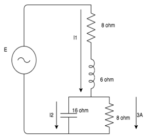
a) 2.54A
b) 6.67A
c) 3.35A
d) 7.65A
Explanation: I3 =(3+j0)A
V2 =I3R=(3+j0)(8+j0)=(24+j0)V
I2=V2/Xc=(j1.5) A
I1 =I2 +I3 =(0+j1.5)+(3+j0)=(3+j1.5)A
I1=(32+1.52)1/2= 3.35A.
6. Find the value of the source voltage from the following circuit.
a) 49.2V
b) 34.6V
c) 65.2V
d) 25.6V
Explanation: I3 =(3+j0)A
V2 =I3R=(3+j0)(8+j0)=(24+j0)V
I2=V2/Xc=(0 + j1.5) A
I1 =I2 +I3 =(0+j1.5)+(3+j0)=(3+j1.5)A
I1=(32+1.52)1/2= 3.35A.
V1 =I1(R+jXL) =(15+j30)V
E=V1 +V2 =(39+j30)V
E=(392+302)1/2= 49.2V.
7. In an AC circuit, resistance 50 Ω, inductance 0.3 H and
capacitance 15 μF is connected to an AC voltage source 25 V, 50 Hz.
Determine the phase difference between current and voltage.
a) 670
b) 540
c) 470
d) 770
Explanation: XL=2πfL, XC=1/(2πfC) f=50Hz and L=0.3H and C=15 μF
XL=2π(50)(0.3) = 94.25 ohm.
XC=1/(2π*50*15*10-6) = 212.21 ohm.
tanϕ = |(XL-XC)|/R = (212.21-94.25)/50 = 2.3592
ϕ=670.
8. What value of direct current must flow through a resistor to
produce the same heating power as an alternating current with a peak
value of 3.5 A?
a) 1.5 A
b) 2.5 A
c) 3.5 A
d) 4.5 A
Explanation: Power in dc circuit = Power in ac circuit (given)
IDC2R = IRMS2R
IDC=IRMS
IRMS=I0/√2 = 3.5/√2 = 2.5 A.
IDC=2.5 A.
This set of Basic Electrical Engineering Multiple Choice Questions & Answers (MCQs) focuses on “Frequency Variation in a Series RLC Circuit”.
1. If the resonant frequency in a series RLC circuit is 50kHz along with a bandwidth of 1kHz, find the quality factor.
a) 5
b) 50
c) 100
d) 500
Explanation: We know that Quality factor is equal to the resonant frequency divided by the bandwidth.
Q=fres/Bandwidth = 50/1 = 50.
2. What is the SI unit for quality factor?
a) Hz
b) kHz
c) MHz
d) No unit
Explanation: We know that Quality factor is equal to the resonant frequency divided by the bandwidth. It is one frequency divided by another hence it has no unit.
3. What happens to the quality factor when the bandwidth increases?
a) Increases
b) Decreases
c) Remains the same
d) Becomes zero
Explanation: Q=fres/Bandwidth
Quality factor is inversely proportional to bandwidth. So, if bandwidth increases quality factor decreases.
4. What happens to the quality factor when resonant frequency increases?
a) Increases
b) Decreases
c) Remains the same
d) Becomes zero
Explanation: Q=fres/Bandwidth
Quality factor is directly proportional to resonant frequency. So, if resonant frequency increases quality factor increases.
5. Resonance frequency occurs when __________________
a) XL=XC
b) XL>XC
c) XL<XC
d) Cannot be determined
Explanation: The frequency of a system is said to be resonating when the value of the capacitive reactance and the inductive reactance is the same.
6. The current leads the supply voltage in a series RLC circuit has its frequency _________ the resonant frequency.
a) Above
b) Below
c) Equal to
d) Cannot be determined
Explanation: Current is leading the voltage indicates capacitor dominating circuit. XC>XL => 1/(ωC) > ωL => ω<1/√LC
So, frequency less than resonant frequency.
7. What is the power factor of a series RLC circuit under resonance condition?
a) 0
b) 1
c) Infinity
d) 100
Explanation: The power factor for a series RLC circuit in resonance condition is always unity because the current is in phase with the voltage under resonance condition.
Φ=00 => cos ϕ = 1 i.e. power factor = 1.
8. The current lags the supply voltage in a series RLC circuit has its frequency _________ the resonant frequency.
a) Above
b) Below
c) Equal to
d) Cannot be determined
Explanation: Current is lagging the voltage indicates inductor dominating circuit. XC < XL => 1/(ωC) < ωL => ω > 1/√LC
So, frequency more than resonant frequency.
9. What is the correct formula for quality factor?
a) Q=BW*fr
b) Q=BW/fr
c) Q=fr/BW
d) Q=fr2
Explanation: The correct formula for quality factor is Q=fr/BW, where fr is the resonant frequency, BW is the bandwidth frequency and Q is the quality factor.
This set of Basic Electrical Engineering Multiple Choice Questions & Answers (MCQs) focuses on “Selectivity”.
1. Shape of the resonance curve depends upon the?
a) Q-factor
b) Voltage
c) Current
d) Either voltage or current
Explanation: The shape of the resonance curve depends on the Q factor because of the equation:
Q=Resonance frequency / Bandwidth. Sharp resonance means high quality factor.
2. A circuit is said to be selective if it has a _____ peak and ____ bandwidth.
a) Blunt, narrow
b) Sharp, narrow
c) Sharp, broad
d) Blunt, broad
Explanation: For a circuit to be selective, it should have high quality factor. And we know that for high quality factor, resonance frequency should be high(peak should be sharp) and bandwidth should be narrow.
3. What is the Q factor of a selective circuit?
a) Very low
b) Very high
c) Zero
d) Infinity
Explanation: For a circuit to be selective, it should have high quality factor. It should have a sharp peak with narrow bandwidth.
4. In selective circuits, higher the Q factor _________ the peak.
a) Sharper
b) Blunter
c) Neither sharper nor blunter
d) Either sharper or blunter
Explanation: Q=Resonance frequency / Bandwidth.
Higher the quality factor, sharper the peak of resonance curve.
5. Q is a measure of _________
a) Resonance
b) Bandwidth
c) Selectivity
d) Either resonance or bandwidth
Explanation: For a circuit to be selective, it should have a high quality factor. It should have a sharp peak with narrow bandwidth.
6. In selective circuits, the resonant frequency lies in the ________ of the bandwidth frequency range.
a) Beginning
b) End
c) Midpoint
d) Cannot be determined
Explanation: In selective circuits, the resonant frequency lies in the midpoint of the bandwidth frequency range.
7. In order for high selectivity, the resistance must be?
a) Small
b) Large
c) Negative
d) Positive
Explanation: For high selectivity, the Q factor should be large and for Q factor to be large, the resistance would be small because Q is inversely proportional to the resistance.
This set of Basic Electrical Engineering Multiple Choice Questions & Answers (MCQs) focuses on “Basic AC Parallel Circuits”.
1. In a parallel circuit, we consider _____________ instead of impedance.
a) Resistance
b) Capacitance
c) Inductance
d) Admittance
Explanation: In a parallel circuit, we consider admittance instead of impedance, where admittance is the reciprocal of impedance.
2. In a parallel circuit, we consider admittance instead of _________
a) Resistance
b) Capacitance
c) Inductance
d) Impedance
Explanation: In a parallel circuit, we consider admittance instead of impedance, where admittance is the reciprocal of impedance.
3. Which, among the following is the correct expression for impedance?
a) Z=Y
b) Z=1/Y
c) Z=Y2
d) Z=1/Y2
Explanation: We know that impedance is the reciprocal of admittance, hence the correct expression for impedance is: Z=1/Y.
4. Which, among the following is the correct expression for admittance?
a) Y=Z
b) Y=1/Z
c) Y=Z2
d) Y=1/Z2
Explanation: We know that admittance is the reciprocal of impedance, hence the correct expression for admittance is: Y=1/Z.
5. What is the unit of admittance?
a) ohm
b) henry
c) farad
d) ohm-1
Explanation: The unit for admittance is ohm-1 because the unit of impedance is ohm and admittance is the reciprocal of impedance.
6. As the impedance increases, the admittance ____________
a) Increases
b) Decreases
c) Remains the same
d) Becomes zero
Explanation: As the impedance increases, the admittance decreases because admittance is equal to 1/impedance.
7. if the impedance of a system is 4 ohm, calculate its admittance.
a) 0.25 ohm-1
b) 4 ohm-1
c) 25 ohm-1
d) 0.4 ohm-1
Explanation: We know that: Y=1/Z.
Substituting the value of Z from the question, we get Y = 1/4 = 0.25 => Y= 0.25 ohm-1.
8. The admittance of a system is 10 ohm-1, calculate its impedance.
a) 10 ohm
b) 0.1 ohm
c) 1 ohm
d) 1.1 ohm
Explanation: We know that: Z=1/Y.
Z = 1/10 = 0.1 => Z = 0.1 ohm.
9. In A parallel circuit, with any number of impedances, The voltage across each impedance is?
a) equal
b) divided equally
c) divided proportionaly
d) zero
Explanation: In parallel circuits, the current across the circuits vary whereas the voltage remains the same. So, voltage across each impedance is equal in parallel circuit.
10. In a parallel circuit, current in each impedance is_____________
a) equal
b) different
c) zero
d) infinite
Explanation: In parallel circuits, the current across the circuits vary whereas the voltage remains the same. So, current in each impedance is different.
This set of Basic Electrical Engineering Multiple Choice Questions & Answers (MCQs) focuses on “Parallel Impedance Circuits”.
1. In an impedance parallel network, the reactive component will ____________ the voltage by 90 degrees.
a) Lead
b) Lag
c) Either lead or lag
d) Depends on the circuit
Explanation: In an impedance parallel network the reactive component will either lead or lag the voltage by 90 degrees.
2. In an impedance parallel network, the reactive component will either lead or lag the voltage by _________ degrees.
a) 0
b) 90
c) 45
d) 180
Explanation: In an impedance parallel network the reactive component will either lead or lag the voltage by 90 degrees.
3. In an impedance parallel network, the reactive component will either lead or lag the ________ by 90 degrees.
a) Voltage
b) Current
c) Either voltage or current
d) Cannot be determined
Explanation: In an impedance parallel network the reactive component will either lead or lag the voltage by 90 degrees.
4. The reactive component in an impedance parallel circuit leads the voltage when the current _________ the voltage.
a) Leads
b) Lags
c) Either leads or lags
d) Cannot be determined
Explanation: The reactive component in an impedance parallel circuit leads the voltage when the current leads the voltage.
5. The active component in an impedance parallel circuit will __________ the voltage.
a) Leads
b) Lags
c) Be in phase with
d) Either leads or lags
Explanation: The active component in an impedance parallel network will always be in phase with the voltage in the circuit.
6. The phase difference between the active component of an impedance
parallel circuit and the voltage in the network is __________
a) 0
b) 90
c) 180
d) 360
Explanation: The active component in an impedance parallel network will always be in phase with the voltage in the circuit. Hence the phase difference is 0.
7. The quadrature component is also known as?
a) Active component
b) Reactive component
c) Either active or reactive component
d) Neither active nor reactive component
Explanation: The quadrature component is also known as the reactive component because the reactive component forms a quadrature with the voltage.
8. Find the expression for the current I from the given circuit.
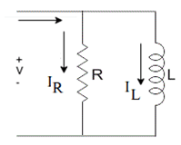
a) I=IL
b) I=IR
c) I=IL+IR
d) I=0
Explanation: I is the total current in the circuit. Since this is a parallel connection, the total current in the circuit is equal to the sum of the currents in each branch of the circuit. Hence I=IR+IL.
9. Find the value of IR if I=10A and IL=8A.
a) 5A
b) 18A
c) 12A
d) 2A
Explanation: We know that I=IR+IL.
10=IR+8 => IR=2A.
10. Find the total current if IL=2A and IR=8A.
a) 3A
b) -3A
c) 7A
d) 10A
Explanation: We know that I=IR+IL.
I=8+2=10A.
